Guide To 2026 FSAE Frame Rule Changes
Keep these resources open during your team’s entire frame design process:
2026 FSAE Rulebook
2026 FSAE Structural Equivalency Spreadsheet (SES)
2025 FSAE Tech Inspection sheet
2026 suspension subteam geometry and loads
2026 ergo subteam packaging
2026 drivetrain subteam packaging
The Guide To 2025 Frame Rule Changes has details about even more rules. (Though some obviously change year to year.)
I hope lots of you got a big start on your 2026 chassis designs using the 2025 Rules and 2025 SES. Chassis Structural Equivalency (SES) review will begin immediately after registration for 2026 FSAE competition. Completing and submitting your SES sooner helps you get approval sooner, and manufacture with confidence. Sending the SES in early helps reviewers by spreading out the review work through fall and winter months. Chassis Tech Inspection is mostly making sure the car matches the SES. We understand engineering changes happen, and there is no penalty in tech order or points for resubmitting after approval. (Try to avoid doing this multiple times.)
Aside from submitting early, the most helpful thing you can do with every resubmission is describe what you have changed and what cells to look at in the SES. Speaking for myself, the longer the process takes, the more tired and cranky I get.
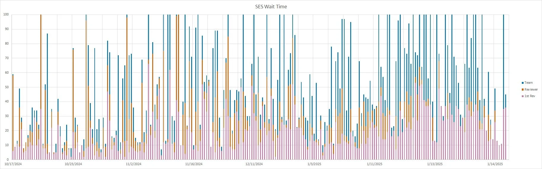
That said, no matter how I plot the data, you spend more time waiting for review than we do waiting for replies. You're doing such a great job, keep it up. We have more great minds helping review every year, and we're all going to work to reduce our turnaround time.
RULE CHANGES AFFECTING ALL TEAMS
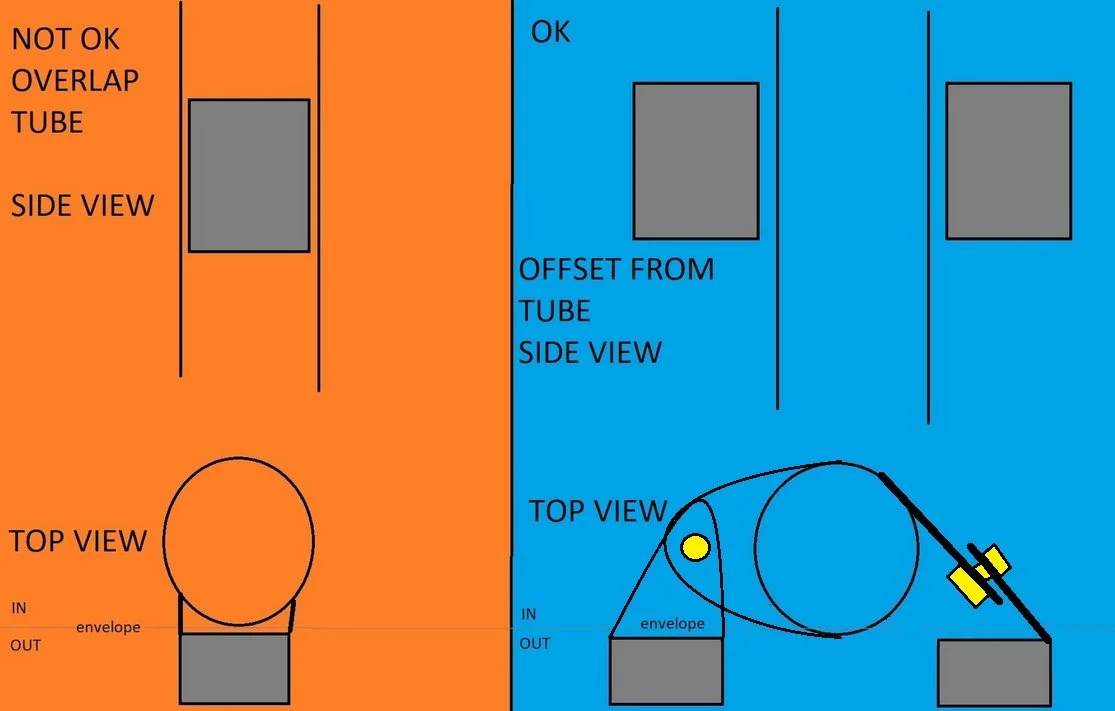
Phasing Out Side View Tubes F.3.4.3, F.5.2.4, F.6.6.3
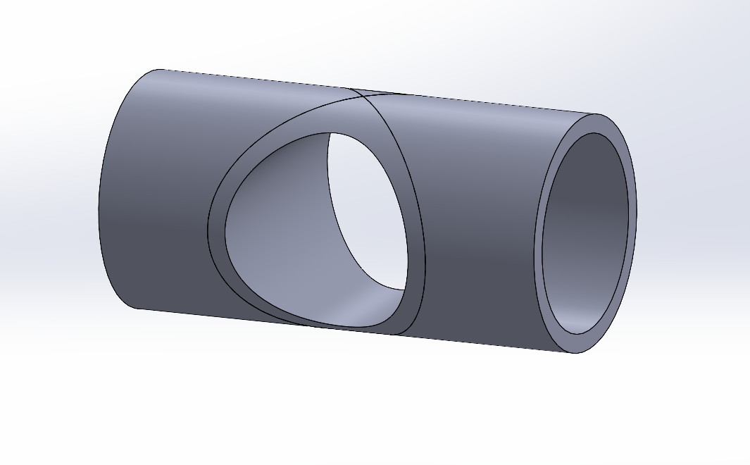
Tubes sticking sideways through regulated members has always been a bad idea. The tube cross section is completely interrupted. Following a failure last year, this is strongly discouraged in 2026 (should), and will be completely illegal in 2027 (must). You should fix this now. There is a three pronged approach:
Welded inserts must be smaller than the OD of the tube they are welded into.
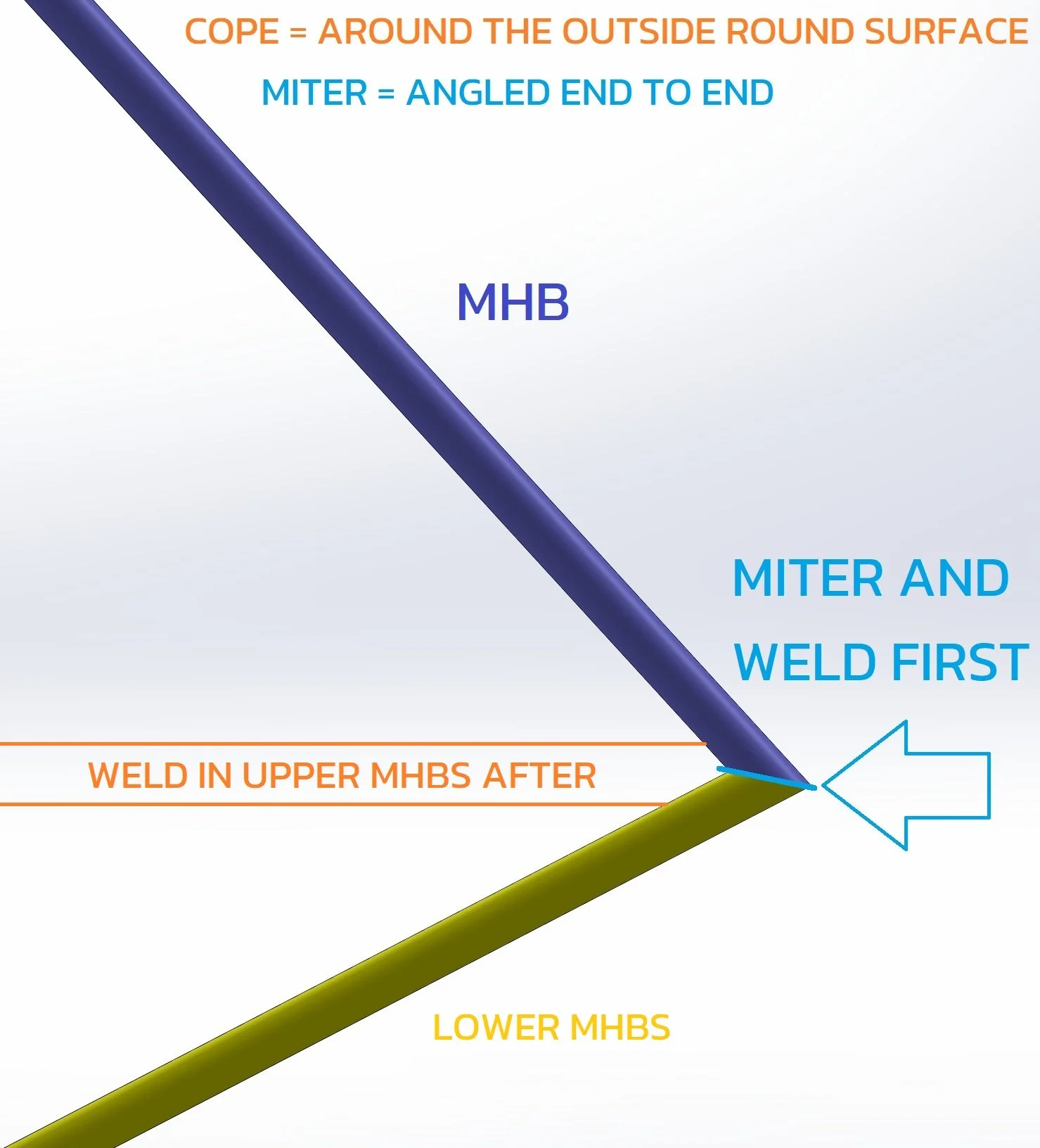
Miter together the ends of multi-piece upper or lower members.
Miter the ends of the MHB to the LOWER MHBS.
There are three bulkheads in tube IC cars, four in tube EV. There is the front bulkhead. FBHS and FBH run to the FH, which is a bulkhead interrupting the longitudinal tubes. SIS runs to MH, which is a bulkhead interrupting the longitudinal tubes. Tractive System protection runs to the rear bulkhead. Don’t interrupt the Front Hoop with tubes, and the Main Hoop must be one piece.
A longitudinal tube such as the Upper MHBS interrupting the MHB to Lower MHBS miter is nearly as problematic as a side view tube. Fully weld the first two tubes inside a node before adding the next tube and fully welding it.
The axial load path through an interrupting tube is reduced to nothing.
Many teams like to have lateral axes at nodes for suspension and powertrain mounts. Use a sensibly sized welded insert, or move the mount inside or outside the elbow of the node, off the centerline.
As of the 2026 competition, it will be legal for the Main Hoop Brace to cope to a bent Shoulder Harness, which must be uninterrupted.
We will use 2026 to develop a policy on open ended Front or Rear Bulkhead tubes, and on Shoulder Harness tubes serving as Main Hoop Brace Supports.
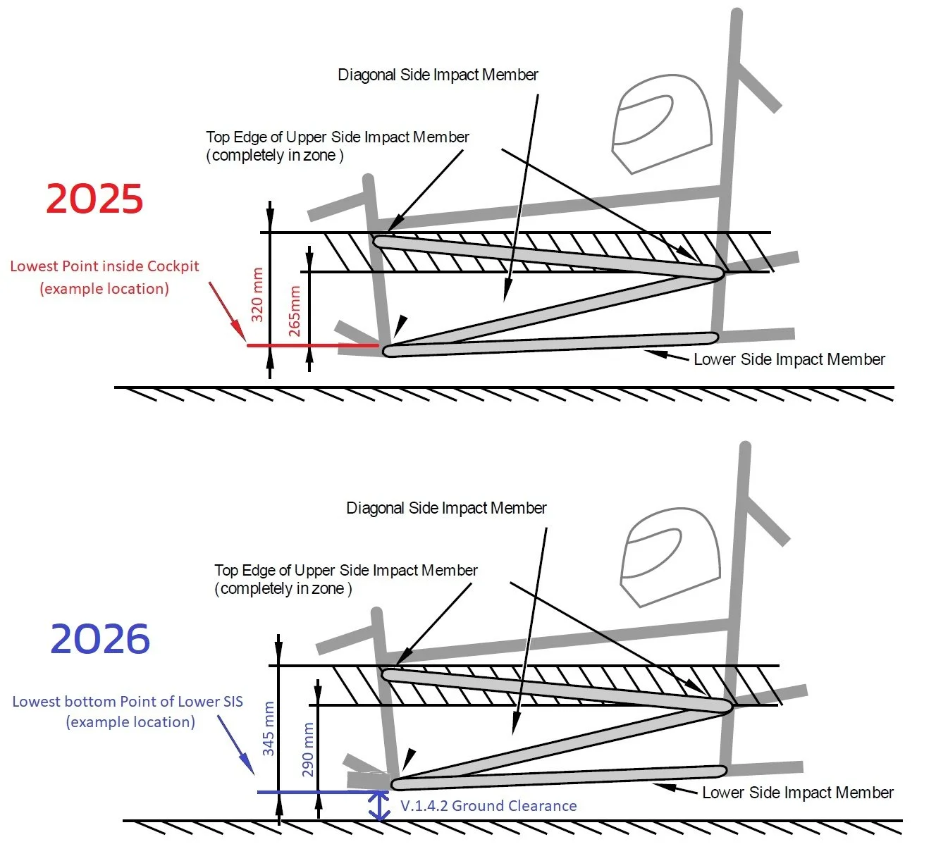
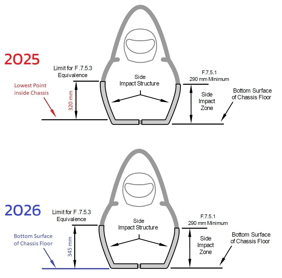
Reference Point Change F.6.4.4, F.7.5.1, F.7.5.3, F.8.5.6, F.11.3.2
The Side Impact Zone, Rear Bulkhead height, and Impact Attenuator height are all exactly the same as 2025. The reference point has moved from the top of the Lower Side Impact Tube to the bottom of the Lower Side Impact Tube. All of the numbers are 25mm different than 2025, but the heights on the cars are exactly the same. Monocoque may be > the height maximum, with the higher section not counted toward equivalence.
Get Everything Off The Head Restraint T.2.8.4
Especially intake manifolds. The head restraint has one job.
Camera Mounts Must Be Implemented Like Wing Mounts F.5.11.2
With tabs at the MH-MHB node, and rotationally free about an axis. No more clamp mounts. Space the camera rearwards to keep it away from the helmet, and prevent it from being driven into a tube in a rollover.
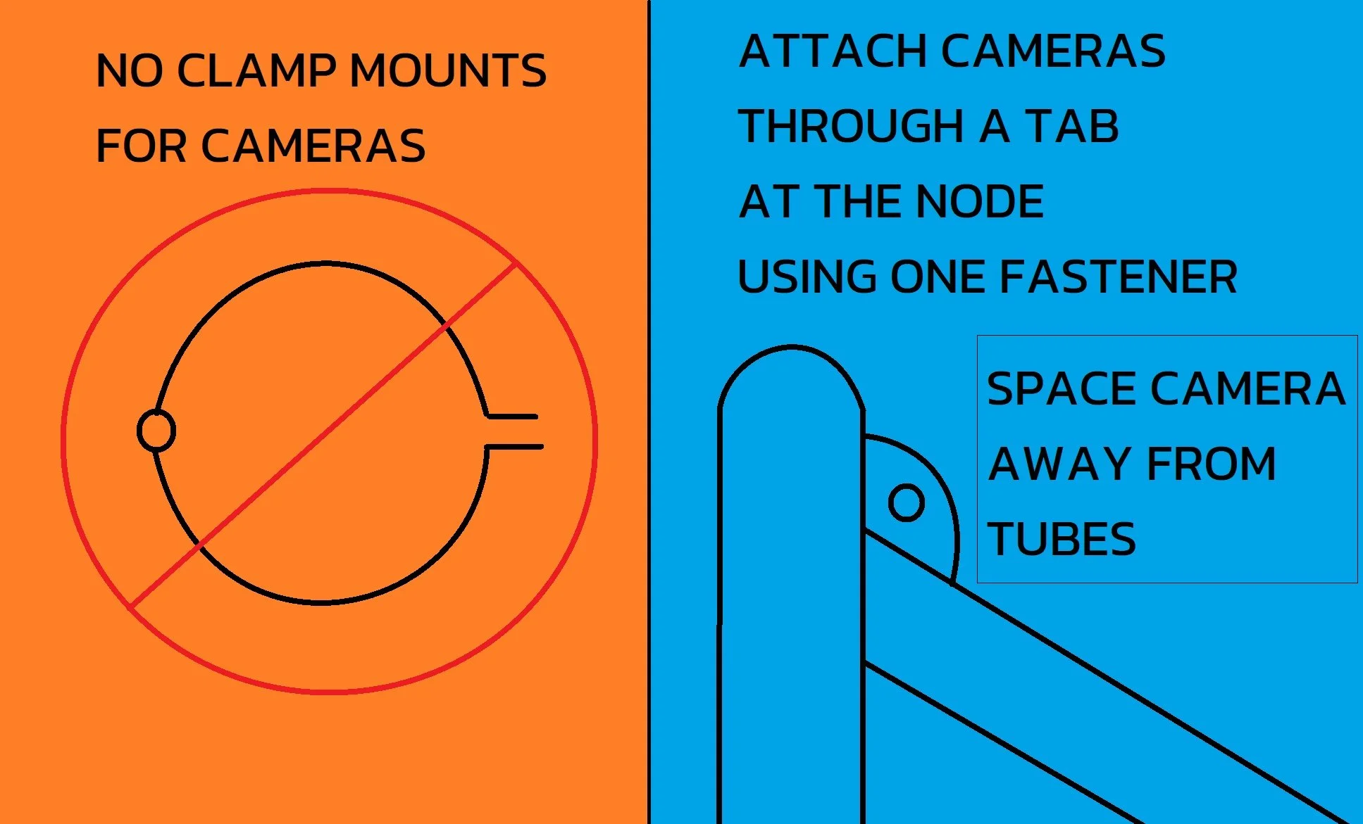
Offset cameras longitudinally from the Main Hoop.
Main Hoop, Main Hoop Braces, and Shoulder Harness structures have one job. F.5.11.4, F.10.5.2.c
End of ramp in. No engine, motor, suspension, or tractive battery mounts on the upper portions of the Main Hoop, Main Hoop Brace spans, or Shoulder Harness structure. The bottom of the Main Hoop below triangulated nodes or mono attachments is fine. The lower MHB node is fine.
Driver Leg Protection T.1.3.1, T.1.3.2
Just a clarification. The driver’s hips must stay below the top of the Upper Side Impact. Ahead of the Front Hoop, feet on the pedals, feet and legs must be below the top of the frame.
LV Battery location T.9.2.1
No change in policy. Reminder that LV batteries must be inside the chassis volume. It does not need to be structural tubing, it does not need to be inside triangulated tubing. Some teams have a non-structural rear suspension box. Inside a suspension box or something that looks like one is a perfectly sensible location for a LV battery. The Tech Inspection sheet explains that in order to be fully inside the chassis, the chassis needs to be higher in front of, behind, to the left of, and to the right of the LV battery. It’s not an extended volume like a rollover envelope. A battery box does not qualify as a chassis, nor does any single halo of material.
RULE CHANGES AFFECTING TUBE TEAMS
FBHS and FHB rules are rewritten, but our policies are unchanged.
Ban on pad eyes for harnesses T.2.4.5.e
Weld Eyes must come from the harness supplier. Weld Eyes must have a shank inserted through a Welded Insert F.3.4.3.
RULE CHANGES AFFECTING EV TEAMS
Accumulators
they’re not hydraulic, now called
Tractive Batteries
Segments are
finally renamed
they’re Modules
Module Attachment To Container F.10.3.2.a-b
We’re ramping existing policy. Modules should be mechanically attached to the container. Without mechanical attachment, Mechanical Cover and Lid attachments must show equivalence to the strength of a welded joint around the entire perimeter.
F.10.3.3, module positive locking, does not require critical fasteners. Just put something in shear for attaching the module that will take the test load. Or do the usual if bolting in tension.
Mechanical attachments will be mandatory in 2027.
Module, Cover, and Lid attachments each require a Positive Locking Mechanism per T.8.3. An overcentering latch does not on its own qualify as positive locking.
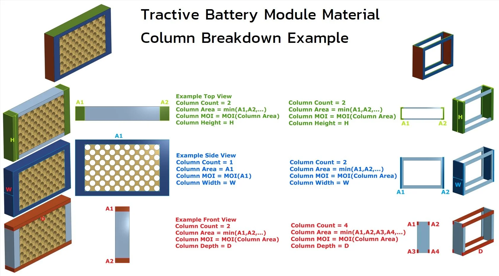
Continuing Module Structure Ramp - F.10.3.4
Cross sectional properties of segment structures must be included for SES calculations of F.10.3.1 compressive loads. Only a cross section that is continuous in area and continuous along its normal can be counted toward equivalence. The minimum principal moment of inertia must be entered for each cross section.
The SES is asking about the structure of a single segment.
removed from the container
aligned lat/long/vert as it is in the car
Structural cross sections are taken with all cells, wiring, cooling, etc. removed. And furthermore, treating hole patterns as one large opening. Just like in your statics class, a column is loaded normal to its cross section, continuous in area and continuous along its normal.
If there are multiple separate cross sectional areas, select only the smallest for area and moment of inertia. Take the minimum cross section, ignoring areas with thicker cross sections. It is also reasonable to ignore the smallest cross section(s), and not include those when counting the number of separate cross sectional areas.
Rear Bulkheads Are Vertical F.11.3.3
The rear bulkhead must be vertical to its full required height, in SIS Zone. This is now a maximum as well as a minimum height.
This is the end of a couple years’ ramp. Especially with accumulators at the rear of the car, we do not want an impact attenuator going below the upper rear bulkhead member. Based on 2025 SES entries, 9 tube teams will be affected. Based on 2025 SES entries, 13 mono rear bulkheads are > 345mm. It is possible they would already pass, and strength can simply be increased, with the structure > 345mm not counted towards equivalence.
And a couple of cheeky teams dangled HV components behind Rear Bulkhead tubes but ahead of differential mounts serving as diagonal equivalence. Don’t do it again.
Ban On Open Ended Pop Rivets F.10.1.6
Hazard of mandrel from open ended rivet shaking loose and shorting HV system. Closed end pop rivets are acceptable
Hub Motor Cable Protection EV.4.1.3.b
Rephrase of existing policy. Reminder that cables for outboard hub motors may only exit the chassis ahead of the Front Hoop and behind the Main Hoop. In between the FH and MH, they must remain inside the primary structure and be firewalled from the driver. Additionally, side exits between the FH and MH for cables, cooling lines or any other item violate F.7.5.3.b in the case of a monocoque.
RULE CHANGES AFFECTING MONO TEAMS
Mono Subframe Attachments Must Be Near Nodes F.7.8.2.a
We were stunned this rule didn’t already exist. Put the car upside down, or back it into something, and the loads coming through the MHBS tubes need to be reacted with attachments. Not making a turn to the middle of the Main Hoop.

Best Mono Practices Collection F.7.1.6, F.7.1.7, F.7.8.8, F.5.6.3
Composite monocoques made in two halves must use scarf joints with structural adhesive for the length of the seam.
Core splice is required between all adjacent core sections in a monocoque.
Core must create a load path ahead of and behind laminated front roll hoops, and around the entire perimeter of Roll Hoop Mounts, Roll Hoop Brace mounts. Highly loaded attachments for anything can’t be floating in space. Make big, straight, wide core load paths connecting all important parts of the monocoque.
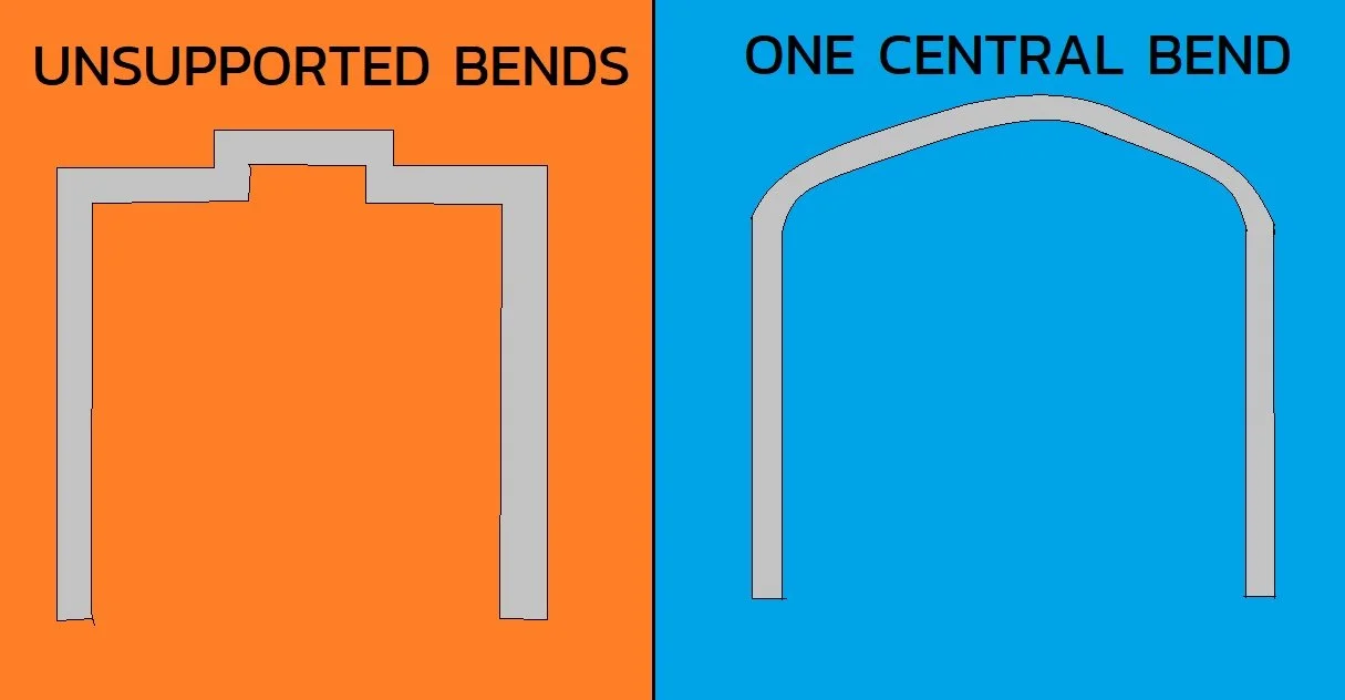
Work on phasing out these square wave front hoops. F.5.6.3 allows for a bend at each roll hoop brace, plus one more in the middle.
Rear Bulkhead Diagonals F.11.3.5.b
Rear differential mounts replacing a rear bulkhead diagonal on mono EVs must be the full height of the rear bulkhead. (Even if taller than the 345mm equivalence limit.)